
Choosing the wrong automatic laser welding machine doesn’t just burn your capital—it drags down output for months. The real cost isn’t the invoice. It’s the downtime, rework, and missed deliveries that follow.
Most mistakes happen before a single machine is ordered. Requirements stay vague. Supplier promises go unchecked. The result is a machine that looks good on paper but can’t hold your takt time or quality spec.
This guide gives you a practical, production-first framework to select a system you won’t regret in twelve months.
What Makes Automatic Laser Welding Different From Semi-Auto or Manual Systems
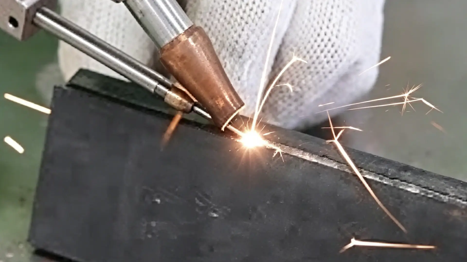
The gap between these three systems isn’t about degree — it’s about who’s in control.
In manual Laser welding, that’s the operator. Every motion, every angle, every trigger pull. The machine delivers power. The human handles everything else. Semi-automatic splits the work — the machine manages wire feed or a fixed Weld path, but the operator still loads parts, aligns fixtures, and starts each cycle.
Automatic laser welding cuts the human out of the weld loop. A CNC laser welding system or robotic laser welding arm runs every motion. Parts come in, welds happen, parts leave — often without a hand touching them.
That difference shapes every real performance gap:
- Throughput: Fully automated cells run at 2–5× the production rate of manual operations. One operator can watch over 2–4 cells at once instead of standing at a single workstation.
- Weld seam quality: Manual reject rates sit at 3–7%. Automatic systems hold under 1–2% through consistent travel speed, stable focus position, and closed-loop monitoring.
- Laser welding speed and precision: Automated motion systems hold ±0.02–0.10 mm repeatability. Manual operators shift position by ±0.5–1.0 mm on long seams. That’s enough to break joint integrity on tight-tolerance parts.
- Labor per part: High-volume automatic lines cut direct labor time per weld by 50–80% compared to manual.
The tradeoff is real. Automatic systems need precise, repeatable fixturing — ≤0.1 mm is the standard target. They take programming time for new parts. Changeovers can run for hours. For high-mix, low-volume work, manual or semi-auto makes more financial sense.
For stable, high-repeat production — battery tabs, sensor housings, surgical implants — automatic is the one setup that actually scales.
Step 1: Define Your Production Line Requirements Before Comparing Any Machine
Most procurement mistakes happen before anyone opens a spec sheet. They happen in the planning stage. Requirements stay vague. Assumptions go unchallenged. “We need a Laser welder” replaces actual engineering thought.
Lock down what your production line demands — in numbers — before you compare a single fiber laser welding machine or CNC laser welding system.
Start with throughput math, not machine catalogs.
Calculate your takt time first. Say your shift runs 7 effective hours (8 hours minus breaks and maintenance) and you need 8,000 welded parts per shift. Your takt time is:
25,200 seconds ÷ 8,000 units = 3.15 seconds per unit
That single number cuts half your options right away. Any laser welding automation integration setup that can’t hold that cycle time — based on real-world uptime, not brochure uptime — is off the list.
Define these constraints before you talk to a single supplier:
- Part geometry and material mix — thickness range, joint types, alloy grades across every SKU
- Required weld seam quality — defect rate targets (e.g., ≤500 ppm major defects), Cpk ≥ 1.33 on critical seam dimensions
- Changeover frequency — running 3–6 SKU changes per shift means your machine needs rapid-reconfigure capability, not just raw laser welding speed and precision
- Uptime requirements — set MTBF ≥ 8 hours and MTTR ≤ 15 minutes per critical station before any comparison starts
- OEE target — realistic new-line design sits at 80–85%; world-class operations push above 90%
Written requirements protect you from the most expensive mistake in capital equipment buying: buying a machine built for someone else’s production line.
Step 2: Choose the Right Laser Type — Why Fiber Laser Dominates Automated Production Lines
Three laser technologies compete for your production line. One wins in automated metal manufacturing — and the numbers make it clear.
Fiber Laser has pushed CO₂ and solid-state YAG aside as the go-to choice for automated lines. Not because of marketing. Because of physics, uptime economics, and real-world integration.
The Core Technical Advantage
fiber lasers run at 1.03–1.08 μm wavelength. Steel, stainless, aluminum, copper, brass — all absorb this wavelength far better than CO₂’s 10.6 μm. The result: higher welding speeds at lower power draw.
beam quality adds to that edge. Industrial fiber systems reach M² of 1.1–1.5 — close to diffraction-limited. That gives you spot sizes of 50–100 μm, pushing power density right where the weld needs it. CO₂ systems tend to measure M² above 2.0.
The efficiency gap is hard to ignore. Fiber lasers turn 30–40% of input electricity into usable laser output. CO₂ systems reach 8–12%. That gap hits your energy bill and cooling load — every shift, every day.
Why Automated Lines Favor Fiber
A robotic laser welding arm needs flexible beam delivery. Fiber cables up to 10–20 meters carry the beam straight to a 6-axis robot head. No mirror-based beam path. No alignment drift. No vibration sensitivity.
Startup response lands in microseconds. High-frequency piercing, on-the-fly welding along conveyors, stitch patterns synced with motion — all of these need near-instant response. Fiber delivers it.
Modern fiber sources talk the same language as your PLC. Native Profinet, EtherCAT, and EtherNet/IP support gives you real-time recipe management, fault alarms, and dynamic power modulation tied to motion control. No custom signal conditioning layers needed.
Uptime tells the final story. Fiber systems are sealed and alignment-free. No mirror cleaning cycles. No resonator gas servicing. A well-maintained fiber line holds 95–98% technical availability — the threshold that makes lights-out operation possible.
Laser Type Comparison at a Glance
| Criterion | Fiber Laser | CO₂ Laser | Solid-State YAG |
|---|---|---|---|
| Wall-plug efficiency | 30–40% | 8–12% | 10–25% |
| Beam quality (M²) | 1.1–1.5 | Often >2.0 | Variable |
| MTBF | >100,000 hrs | 10,000–20,000 hrs | Moderate |
| Maintenance burden | Minimal | Frequent optics/alignment | Moderate |
| Reflective metal capability | Excellent | Limited | Limited |
| Robotic integration | Direct fiber cable | Mirror beam path | Fiber or mirror |
Fiber Is the Right Call Here
Pick fiber if your production line fits any of these:
- Primary materials are metals in the 0.5–30 mm thickness range
- Reflective alloys — aluminum, copper, brass — show up anywhere in your part mix (critical for EV busbars, battery tabs, motor components)
- Cycle time targets demand 2–3× the throughput of legacy CO₂ systems
- Lights-out or near-lights-out operation is part of your OEE strategy
One exception worth noting: non-metals — acrylic, wood, textiles — give CO₂ an absorption edge. For pure metal production lines, that exception almost never comes up.
Step 3: Match Laser Power and Beam Quality to Your Material and Thickness
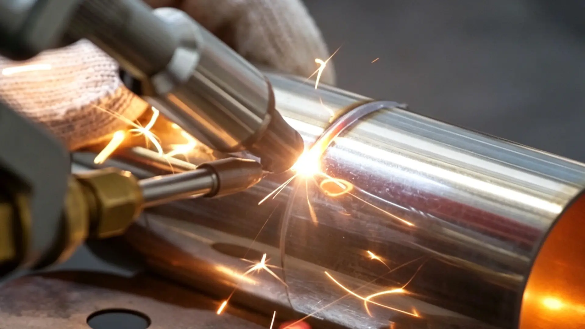
Spec sheet power ratings mislead buyers into the wrong machine — every time. A 6 kW laser sounds impressive. But pair it with poor beam quality, and a 3 kW system with tighter focus beats it on the same material.
Here’s why: power density is what cuts and welds metal. That’s the energy packed per unit area at the focal point. Raw wattage tells you half the story. That’s it.
Power-to-Thickness: The Numbers You Need
Start here — match your material thickness to the right power bracket first:
| Material | Thickness | Recommended Power |
|---|---|---|
| Any metal (thin sheet) | Under 2 mm | 100–500 W |
| Steel / stainless / aluminum | 2–10 mm | 1–3 kW |
| Heavy sections | Above 10 mm | 4 kW+ |
| Mild steel | Up to 25 mm | 1.5–6 kW |
| Stainless steel | Up to 20 mm | 1.5–4 kW |
| Aluminum | Up to 12 mm | 1.5–3 kW |
Some concrete machine pairings to illustrate: a 1.5 kW fiber Laser handles up to 6 mm steel. A 40 kW fiber system reaches 50 mm. An Nd:YAG system — regardless of configuration — tops out around 10 mm. Full stop.
Beam Quality: The M² Number You Can’t Ignore
M² measures how tight a real beam focuses compared to a perfect Gaussian beam. Lower M² means a smaller spot size, higher power density, and cleaner welds.
Industrial fiber systems hold M² between 1.1–1.5. That gives you spot sizes of 50–100 μm — tight enough to drive fast, deep penetration welds.
One measurement detail to watch: your supplier may give you FWHM beam diameter data from mechanical measurements. Multiply that number by 1.7 to get the equivalent 1/e² diameter. These two metrics are not the same thing. Mixing them up gives you an overly optimistic picture of focusability — and leads to bad purchasing decisions.
The Matching Procedure
- Confirm your material type and thickness range across every SKU on your line
- Pick the power bracket that covers your thickest cross-section
- Verify the machine delivers enough power density at the focal spot — not just raw wattage
- Request M² data from the supplier. Or run ISO-standard beam characterization yourself: measure the beam diameter at 10+ positions around focus, spread across the Rayleigh distance and beyond 2 Rayleigh lengths
- Run a test weld. Check seam quality at your actual production feed rates
The rule for thicker materials: thicker material demands higher wattage and better beam focusability — both together. A high-power laser with poor beam quality will lose to a lower-power system with a tight, well-focused beam. Power density does the work. Wattage alone does not.
Step 4: Evaluate Key Process Features That Impact Weld Quality on Production Lines
Weld Quality doesn’t fail at the final inspection station. It fails upstream — in the process parameters nobody checked closely enough. The drift is quiet. It builds in small steps.
Four variables drive most laser weld quality outcomes on production lines: laser power, welding speed, defocus distance, and joint fit-up. Get these right, and your seam quality holds. Let any one drift, and the damage compounds fast.
Here’s what the experimental data shows:
- Laser power (LP) is the dominant variable. Power shifts of ±10–20% move weld penetration and width by more than 30%. On a live production line, that gap separates a compliant joint from a reject.
- Welding speed controls energy per unit length. A 20–40% speed change — without a matching power adjustment — reduces weld cross-section by 30–40%. Takt time pressure makes this a real risk on high-volume lines.
- Defocus distance gets underestimated. Moving the focal point just 1–2 mm off target cuts penetration depth by more than 20% at the same power and speed. That’s a big loss from a small shift.
- Joint fit-up and fixture repeatability close the loop. Automated lines need to hold root opening to 0–1.5 mm. Past 2–3 mm, lack-of-fusion defects climb fast. Fixture repeatability targets of ≤0.1–0.2 mm at the weld location aren’t optional — they’re the baseline requirement.
Where Porosity Comes From (It’s Not What Most Assume)
Here’s a finding that surprises most engineers: porosity shows statistical independence from laser power, speed, and defocus distance. In experimental studies, LP, WS, and DD had no measurable effect on porosity rates.
So chasing power calibration to fix a porosity problem wastes time. The real suspects are:
- Shielding gas flow outside ±10–15% of setpoint
- Surface contamination — oil, scale, residual moisture
- Keyhole instability from inconsistent joint geometry
Set shielding gas flow to 15–25 l/min for standard applications. Audit gas delivery at the nozzle — not just at the regulator. Those are two different readings.
A Practical Evaluation Checklist
Before accepting any machine — or diagnosing a line that’s already underperforming — run through these checks:
- Pull 7–30 days of logged process data — power, speed, focus offset. Find the percentage of readings outside your WPS limits. Target: >95–99% in-spec. Excursions above 1–2% need root cause analysis, not a pass.
- Run macro-etch samples on 30–50 welds per critical joint type. Plot penetration depth against power and speed. PD variability above ±10–15% of nominal while power stays stable points to focus drift or joint gap issues.
- Measure actual joint gaps across 50–100 consecutive parts at representative stations. Defect rates tied to specific fixtures mean locating pins and clamp wear need checking — not the laser source.
- Validate robot path accuracy with laser trackers or contact gauges. Tip position needs to land within ±0.5–1.0 mm at every weld start and end point. Torch or beam angle deviations beyond ±5° are alarm-level events in any well-run robotic cell.
- Check calibration dates on all power sources and measurement tools. The standard interval is ≤12 months. Worn optics and contact tips push variability up in both power and feed rate — long before the reject rate gives it away.
The core idea here is straightforward: laser welding weld seam quality is a process output, not a machine spec. The machine makes consistency possible. Your process controls decide whether you get it.
Step 5: Assess Automation Level and Production Line Integration Capability
Buying a high-spec CNC laser welding system and dropping it into a poorly integrated line is like installing a Formula 1 engine in a car with no transmission. The power is there. None of it reaches the wheels.
Automation level and laser welding automation integration capability are the two things most procurement teams check last. Most regret that decision.
Start with a hard inventory. Walk every station. For each one, assign a score from 0 to 4:
- 0 — Manual, zero data capture
- 1 — Semi-automatic, no network connection
- 2 — Automatic, local PLC only
- 3 — Automatic PLC + plant network + basic data logging
- 4 — Connected to MES/ERP with rich, real-time data
Lines averaging ≥2.5–3 are ready for MES and IoT-layer integration. Lines below 2 need basic automation gaps closed first. Deeper integration won’t help until those gaps are fixed.
The Integration Thresholds That Matter
Your floor needs to clear these benchmarks before any robotic laser welding arm goes live:
- ≥90% of critical stations have networked sensors at the device level
- ≥80% of machines run under PLC or robot controller — not relay logic
- ≥70–80% of machines have digital I/O ready for line control — no hardware changes needed
- All new equipment supports EtherNet/IP, PROFINET, or Modbus TCP — custom gateway workarounds add cost and create failure points
Equipment older than 15–20 years often has no native Ethernet at all. Check each asset before you assume it integrates. Document its I/O availability, spare ports, and whether it can accept external start/stop and recipe commands.
What Integration Delivers
The numbers make the case. Automated lines running laser welding automation integration at depth tend to hit:
- 50–100%+ throughput increase — moving from manual multi-shift to synchronized automated operation
- 20–50% defect rate reduction — where human setup inconsistency drove most quality problems
- 20–40% direct operator reallocation at the line — a smaller, higher-skilled technician layer takes over
Changeover time is the metric most teams forget to target. High-mix lines should hit SMED-style changeovers under 10–15 minutes. Miss that benchmark and high automation turns into a liability. Fast welding gets interrupted by slow transitions — and that gap eats your gains.
Integration isn’t something you buy from a machine supplier. It’s a readiness condition you build into your production setup before the machine ever arrives.
Step 6: Calculate Total Cost of Ownership, Not Just Purchase Price
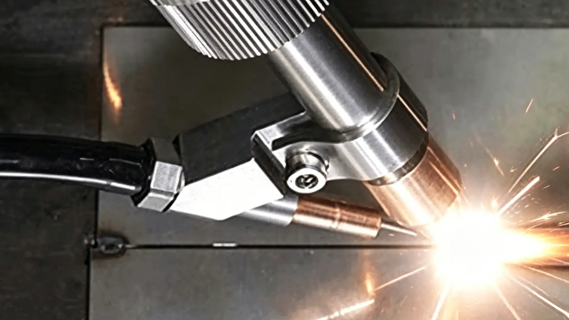
The purchase price is the number on the quote. It is almost never the number that matters.
Take a fiber laser welding machine running a 10-year production lifecycle. Annual operating costs alone — energy, labor, consumables, software licenses, insurance — can reach $91,500 per year. Stretch that across a decade and you’re looking at $915,000 in operating costs. That’s before a single maintenance call, unplanned downtime hour, or decommissioning fee. The sticker price? A fraction of that total.
Most procurement teams skip this calculation. Then they wonder why the “cheaper” machine costs more by year three.
Build the TCO Formula Before You Build the Shortlist
The formula itself is straightforward. Filling it in is the hard part:
TCO = Purchase price + freight + installation + training + initial spares + (annual energy + labor + consumables + licenses + insurance + maintenance + downtime) × useful life + decommissioning − resale value
Use a 5–7 year technology lifecycle as your ownership horizon for CNC laser welding systems and robotic laser welding arm configurations. Some high-utilization lines justify 10 years. Pick the horizon that reflects your real replacement cycle — not the one that makes the math look better.
The Cost Buckets You Can’t Afford to Miss
Year 0 — Acquisition costs:
– Invoice price
– Freight and logistics
– Installation and commissioning labor
– Operator and maintenance training
– Initial spare-parts inventory
Annual recurring — Operating costs:
– Energy draw (kWh × your facility’s energy rate)
– Direct operator labor tied to the machine
– Consumables — protective lenses, nozzles, shielding gas
– Software licenses and connectivity fees
– Laser welding machine maintenance contracts and preventive service
The hidden line item: downtime. Price it at your actual lost-output cost per hour. A machine that goes down twice per month at $2,000 per hour adds $48,000 per year to its real cost. None of that shows up on any spec sheet.
Normalize for Real Comparison
Raw TCO numbers are tough to compare across machines with different capacities. Convert everything to the same units:
- TCO per year = Total TCO ÷ useful life
- TCO per unit produced = TCO per year ÷ annual output
A machine with a higher purchase price but tighter laser welding weld seam quality control and lower reject rates can deliver a lower cost-per-good-part. That’s the number that belongs in your budget conversation — not the invoice total.
Show management the gap between lowest price and lowest TCO side by side. That single comparison is often what gets the right machine approved.
Step 7: Verify Safety Compliance and Certifications Before Final Selection
A machine that welds well but ships without the right certifications can shut your production line down faster than any mechanical failure.
laser welding equipment sold into industrial environments carries real regulatory weight. The certifications you need depend on where you operate and what you produce. But the core requirements stay the same: CE marking (EU), FDA registration (US medical device supply chains), and ISO 11553 laser safety compliance. No scanned PDF documentation for each of these? That’s your answer right there.
Run these checks before signing any purchase order:
- Demand PDFs, not photos — scanned certificates only; image files are not valid documentation
- Check validity dates — certificates must be current, not expired or up for renewal
- Cross-verify issuing bodies — certificates must come from accredited third-party bodies, not self-declarations
- Confirm laser class compliance — Class 4 systems need documented safety enclosures, interlocks, and operator PPE protocols
- Review corrective action history — suppliers with repeat open non-conformances are a liability, not a bargain
One number worth targeting: 100% of safety-critical documentation must be current, version-controlled, and assigned to a named responsible party. Any gap is a procurement risk. Full stop.
Conclusion
Selecting an automatic laser welding machine is a production decision, not a procurement checkbox. The winners start with takt-driven requirements, match laser power and beam quality to real materials, and validate integration capability and TCO before signing.
Done right, you’ll gain predictable throughput, consistent weld seam quality, and lower lifetime cost. Done wrong, you’ll spend years fighting downtime and rejects.
Ready to match a fiber laser welding machine to your exact production line—without overspending or overcomplicating? MaxWave designs and builds systems in-house, tests with your real parts before shipment, and provides integration-ready solutions that fit your takt time and quality targets.

0 Comments