
MAXWAVE GALVO LASER SOLDERING SYSTEM
Galvo Laser Soldering Machine That Reaches Multiple Joints with Less Mechanical Movement
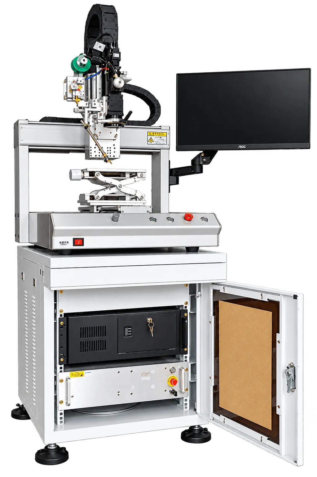
Built for Faster, Simpler Everyday Welding
01
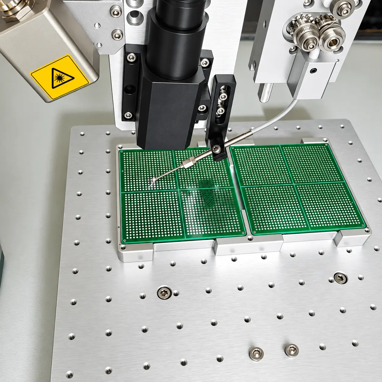
Less Board Repositioning
Move between solder points without constantly repositioning the PCB within the scanning area.
02
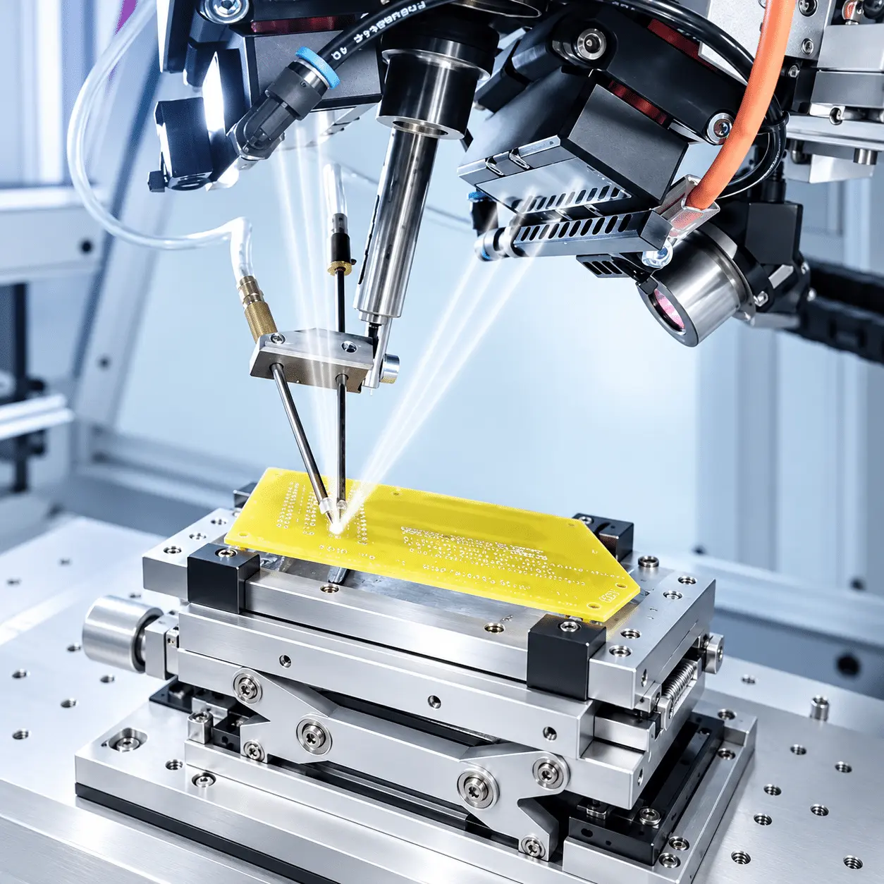
Less Manual Soldering
Let the laser heat each selected joint without manually applying a soldering iron to every point.
03
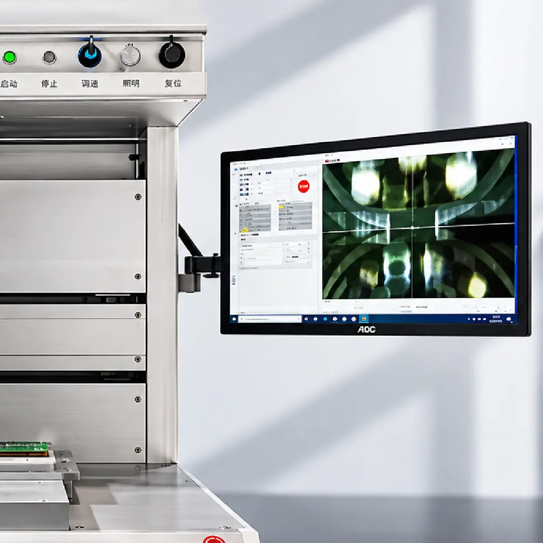
Easier Joint Monitoring
View the soldering area on screen without constantly leaning over the workpiece to follow each joint.
Can This Laser Soldering Machine Handle Your Parts?
Laser Soldering Joint Examples
See how this laser soldering machine can be configured for PCB pads, flexible circuits, connector pins, and wire-to-board connections. Share a drawing or sample to confirm process suitability.
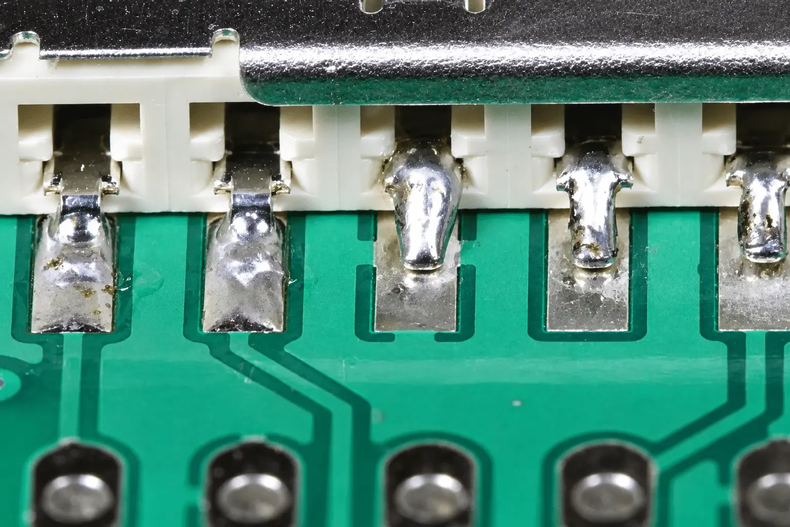
SAMPLE 01
PCB & SMT Solder Joints
SELECTIVE HEATING | PCB PADS
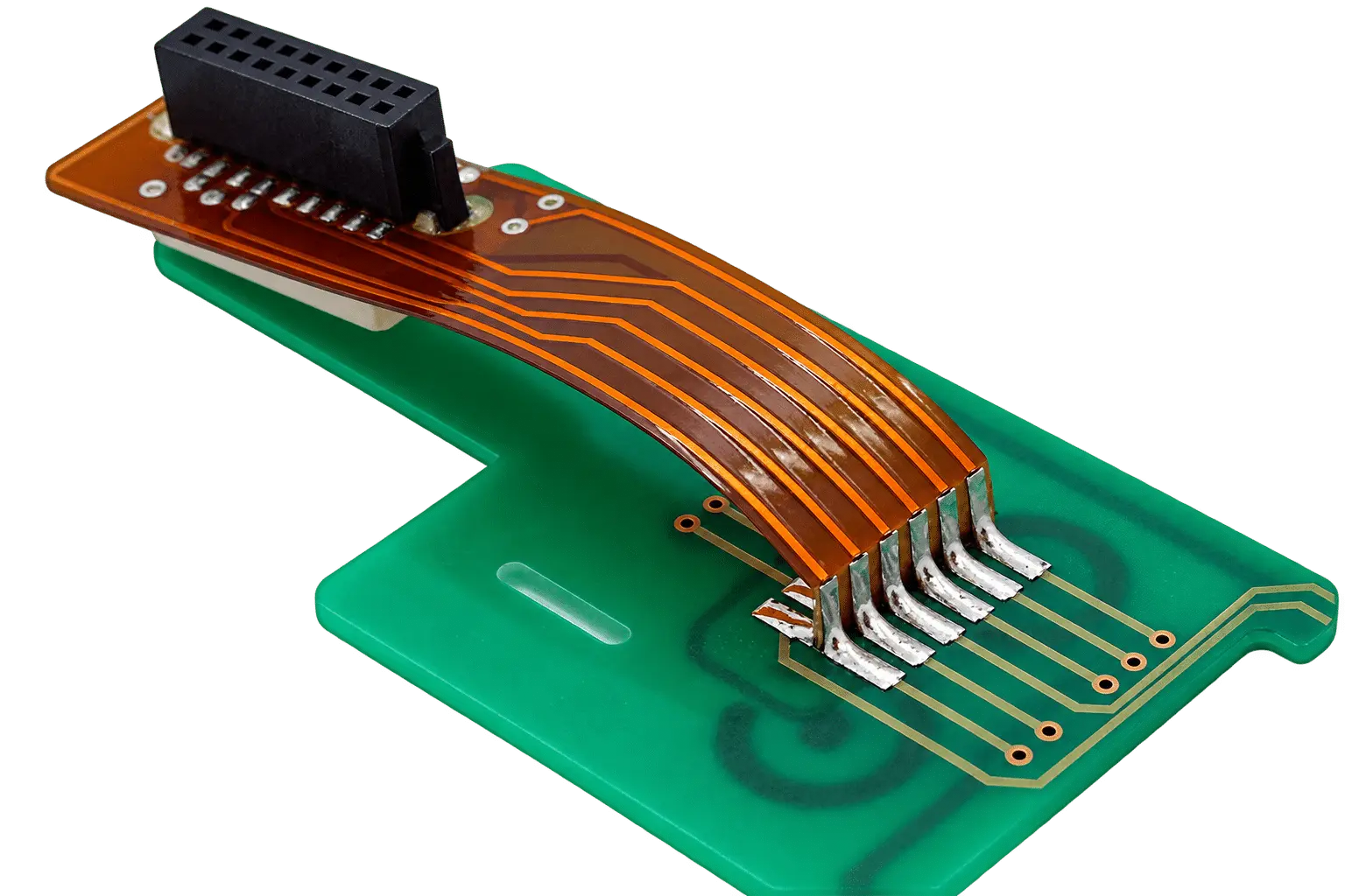
SAMPLE 02
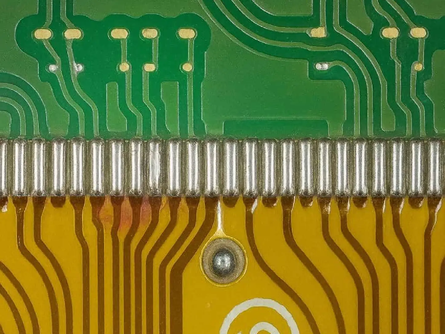
FPC-to-PCB Connections
NON-CONTACT HEATING | FLEX CIRCUITS
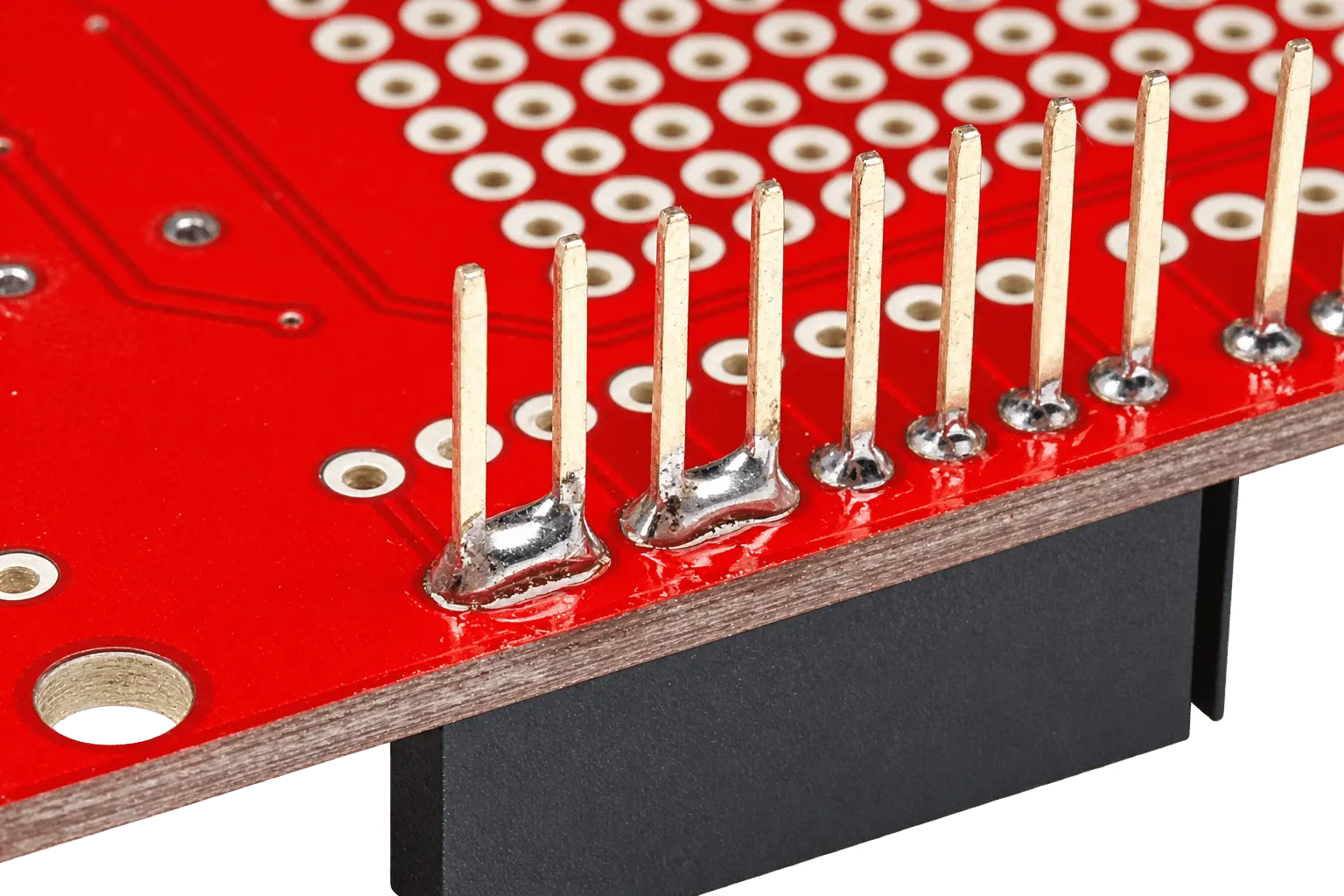
SAMPLE 03
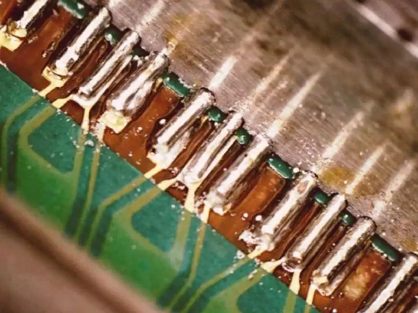
Connector Pin Soldering
GALVO SCANNING | MULTIPLE PINS
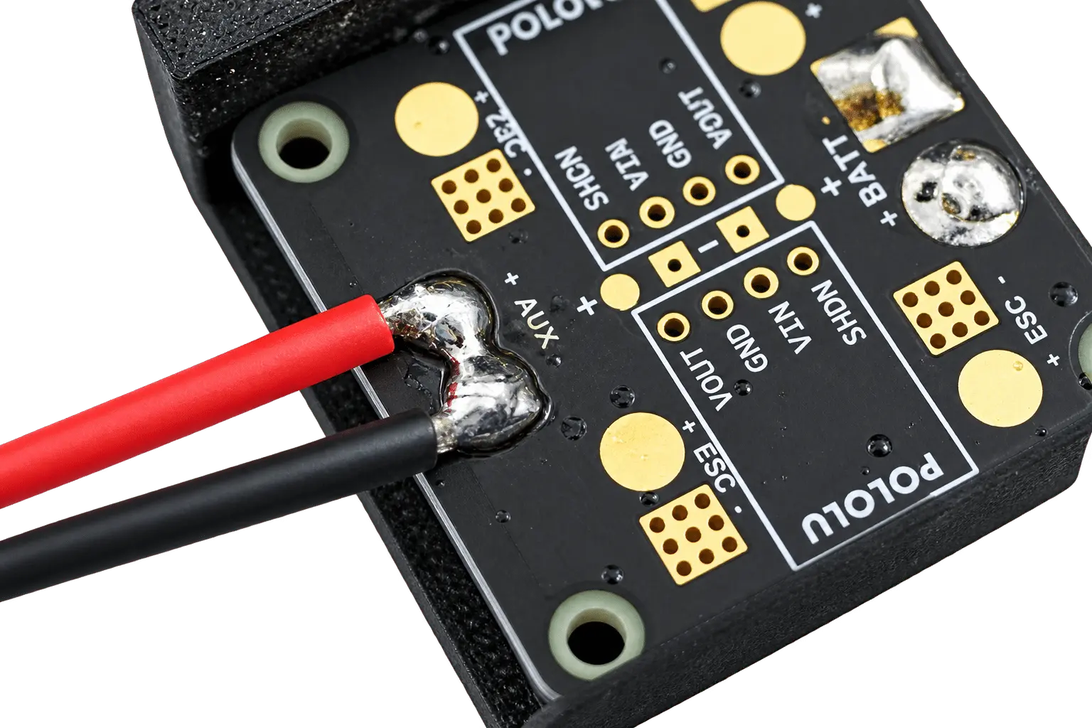
SAMPLE 04
Wire-to-Board Soldering
TARGETED HEATING | WIRE LEADS
Where It Fits

PCB & PCBA Manufacturing

Consumer Electronics

Automotive Electronics
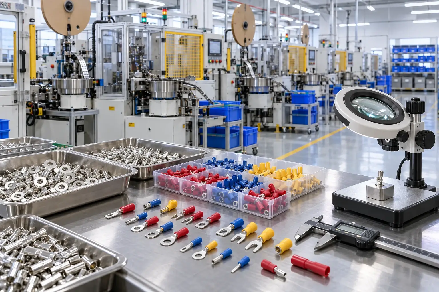
Connector & Terminal Manufacturing
What Makes This Laser Soldering Machine Different?
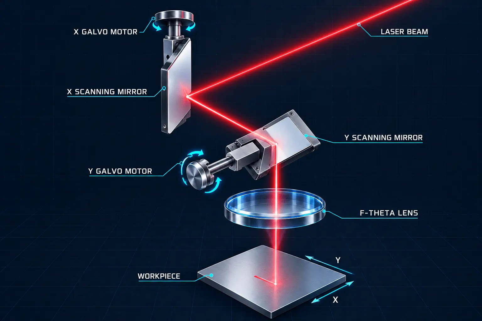
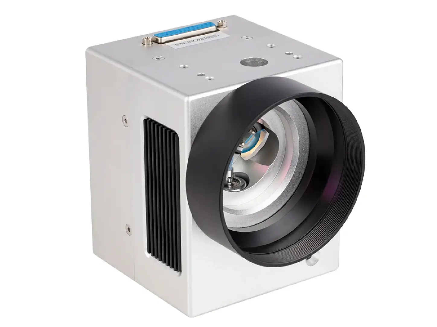
Move Between Solder Joints Without Repositioning the PCB
We use a galvo scanning head to direct the laser between programmed solder points within the scanning field, reducing the need to reposition the PCB for each joint. That means less mechanical movement, smoother multi-point processing, and a more efficient soldering workflow for repeated PCB layouts.
POSITIONING Programmed Solder Points
APPLICATION Multi-Point PCB Soldering
Apply Heat Where the Solder Joint Needs It
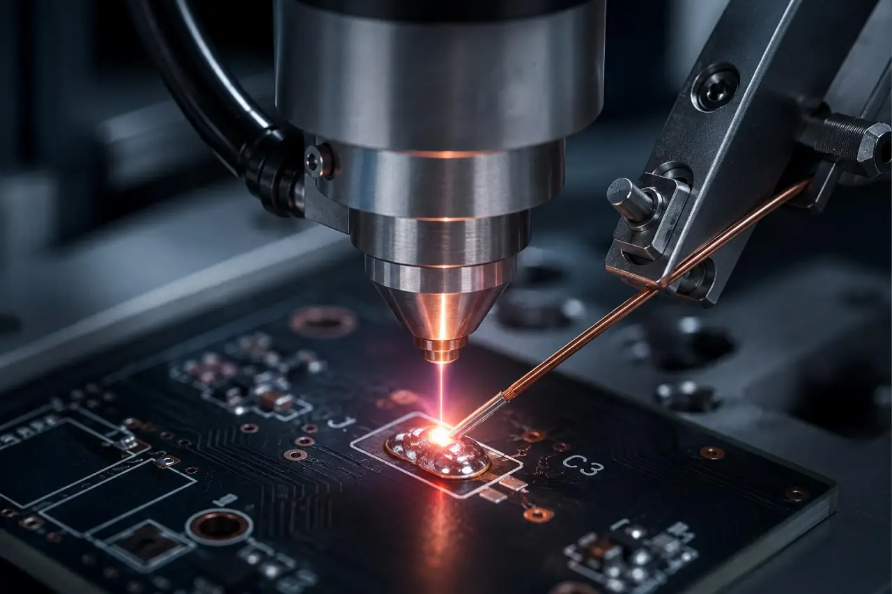
We focus laser energy on selected solder joints without pressing a soldering tool against the PCB or FPC, helping limit unnecessary heating and mechanical contact around nearby components. That means less concern about heat-sensitive parts and a more controlled soldering experience when working with delicate electronic assemblies.
METHOD Non-Contact Soldering
APPLICATION PCB · FPC · Connectors
Keep Solder Joint Temperature Under Control
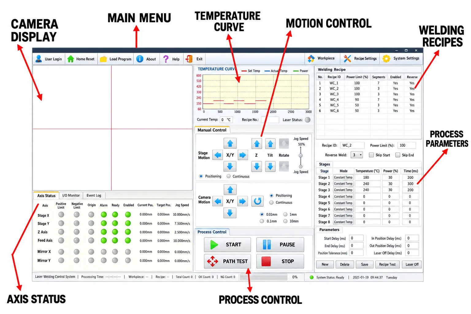
With optional infrared temperature feedback and closed-loop control, we monitor solder joint temperature during processing and adjust laser output according to the selected temperature target. That helps reduce overheating and insufficient solder melting, giving operators a more predictable soldering process and greater confidence when working with heat-sensitive components.
CONTROL Closed-Loop Laser Output
MODULE Optional IR Feedback
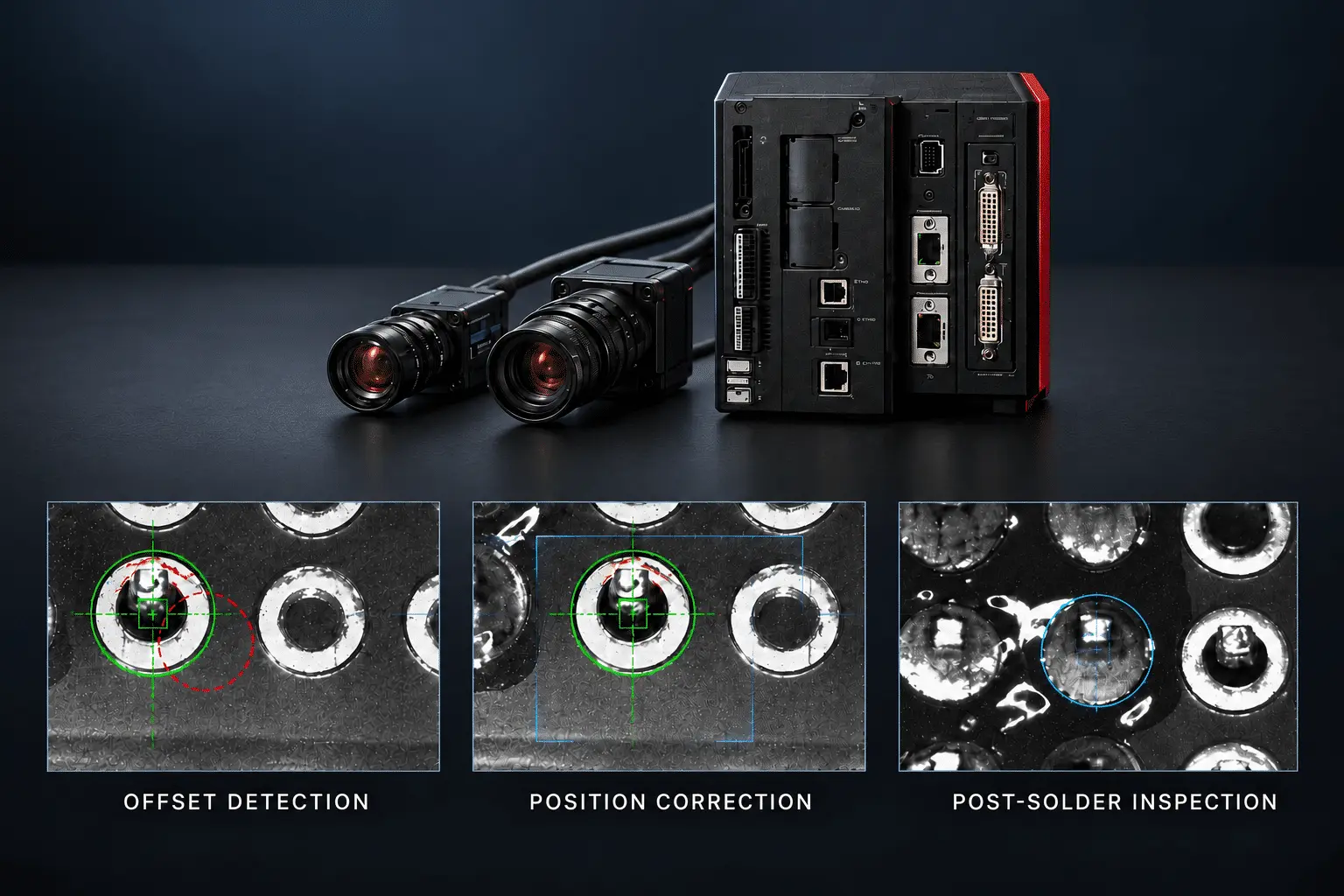
See Small Solder Points Before Heating
With optional coaxial CCD vision, we provide a camera view aligned with the laser optical path, allowing operators to observe solder joints and check positioning before heating. That means easier alignment on small PCB pads, less uncertainty during setup, and greater confidence when soldering densely arranged electronic components.
ALIGNMENT Solder Point Observation
APPLICATION Small Pads · Dense Layouts
SOLDER FEEDING PERFORMANCE
More Consistent Solder Joints Start With Controlled Feeding
For compatible applications, an optional programmable solder feeder works with the laser soldering machine to control wire delivery and heating timing across repeated joints.
01 · SOLDER AMOUNT CONTROL
Deliver the Right Amount of Solder
Program the solder wire feed length to match different joint requirements, helping reduce excessive solder and insufficient filling during repeated operations.
SOLDER DELIVERY
Programmable Feed Length · Controlled Solder Supply
02 · FEEDING & HEATING COORDINATION
Keep Solder Feeding in Step With Laser Heating
Coordinate solder feeding with the laser heating sequence, helping maintain a smoother soldering process and reducing interruptions caused by inconsistent material delivery..
PROCESS COORDINATION
Wire-Feed Timing · Laser Heating Sequence
03 · ADJUSTABLE FEEDING PARAMETERS
Adapt Feeding Settings to Different Solder Joints
Adjust wire feed length and speed for compatible PCB pads, connector pins, and other soldering tasks, giving operators greater flexibility when switching between products.
FEED ADJUSTMENT
Wire Length · Feed Speed · Joint Requirements
Choose the Right Laser Power for Your Soldering Job
The right laser soldering machine configuration depends on solder pad size, required solder volume, and thermal demands—not PCB dimensions alone.
POWE
BEST FOR
TYPICAL SOLDERING WORK
WHY CHOOSE IT
20–50W
Fine-Pitch & Micro Components
Small solder pads, miniature sensors, micro-connectors
Suitable for small solder volumes and localized heating
80–100W
General PCB & FPC Soldering
PCB solder pads, FPC connections, small connector pins
A practical power range for everyday precision soldering
150–200W
Larger Pads & Connectors
Wire-to-PCB joints, larger connector pins, copper pads
More heating capacity for joints with greater thermal mass
300W+
High-Thermal-Mass Soldering
Large terminals, heavy copper pads, high-current connections
Higher-power configurations for demanding soldering tasks
PROCESS CONTROL OPTIONS
Standard vs Temperature-Controlled Laser Soldering
Select a laser soldering machine setup based on joint sensitivity, process repeatability, and whether closed-loop temperature feedback is needed.
STANDARD SCANNING
Galvo Laser Soldering
For repeatable solder joints with consistent materials and proven process settings.
Consistent Joints
Suited to similar pads and repeated soldering tasks.
Preset Parameters
Use validated laser settings for routine production.
Simpler Setup
No integrated temperature-feedback system required.
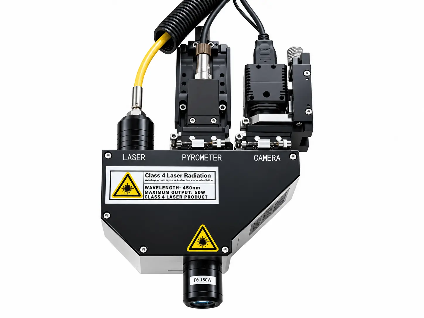
TEMPERATURE-CONTROLLED
Temperature Feedback Soldering
For delicate electronics that require closer control of soldering temperature.
Sensitive Components
Useful for FPC, sensors, and heat-sensitive assemblies.
Closed-Loop Control
Adjust laser output using real-time temperature feedback.
Coaxial Monitoring
Supports visual observation when equipped with the required camera.
PROCESS COMPARISON
Laser Soldering Machine vs Manual Soldering & Hot Bar
Compare operator skill, heat input and post-weld work across common fabrication jobs.
Manual Soldering
Direct Tip Heating
A heated iron contacts each pad to melt solder and form a joint.
Flexible for Repairs
Suitable for prototypes and repairs, but each joint requires manual attention.
Operator-Dependent Results
Heating time and solder feeding depend on the technician’s skill and technique.
Hot Bar Soldering
Heat and Pressure
A heated thermode applies controlled heat and pressure to solder aligned contacts.
Multiple Joints per Cycle
Suitable for soldering multiple aligned FPC contacts in a single cycle.
Fixed Layout Requirements
Different joint patterns may require adjustments to thermodes or holding fixtures.
Galvo Laser Soldering
Non-Contact Heating
A focused laser heats selected solder joints without pressing on delicate components.
Programmable Multi-Point Scanning
Galvo scanning moves the beam rapidly between programmed soldering positions.
Optional Temperature Feedback
Closed-loop control can adjust laser power based on measured solder joint temperature.
FREE SAMPLE TEST
See Your Soldering Results Before You Buy
Send us your PCB, FPC, or connector samples. We’ll evaluate how a laser soldering machine can handle your joint geometry, solder material, and heating requirements, then recommend a suitable configuration.
01
Share Your Joint Details
PCB/FPC Sample · Pad Size · Solder Material · Drawing
02
Match the Soldering Setup
Laser Power · Spot Size · Scan Path · Temperature Control
03
Test & Record the Joint
Sample Soldering · Joint Close-Ups · Process Video
04
Review Before Ordering
Soldering Results · Tested Settings · Recommended Setup
WHAT YOU’LL RECEIVE
A Clear Result Before You Order
Solder Joint Photos
Inspect solder coverage, joint appearance, and nearby components.
Soldering Test Video
See the actual laser soldering process on your sample.
Recommended Setup
Review suitable laser settings and configuration options.
PACKAGE & CONFIGURATION
Know What Your Laser Soldering System Includes
Explore the core system components, routine supplies, and available options to build a laser soldering setup that fits your application.
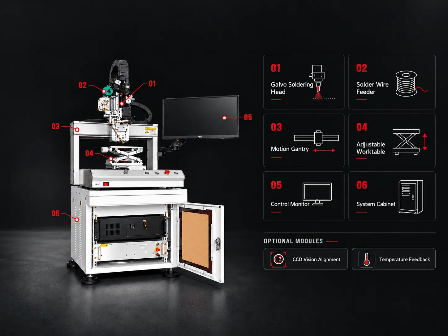
01 Included With the Machine
Laser Source
Power selected for your solder joint and heating requirements.
Galvo Scanning Head
Directs the laser beam across programmed soldering points.
Scanning Lens
Matched to the required working field and solder spot size.
System Controller
Coordinates laser output and scanning movements.
Soldering Software
Sets soldering positions, heating parameters, and process sequences.
02 Consumables & Spare Parts
Solder Wire or Paste
Selected according to the soldering method and joint requirements.
Flux & Cleaning Supplies
Application-dependent materials for suitable solder joint preparation.
Optical Protection Parts
Replacement protection parts for applicable optical assemblies.
Feeding Components
Spare guides and feeding parts for compatible wire-fed systems.
03 Optional Add-ons
Temperature Feedback
Adjusts laser heating through real-time temperature monitoring.
Coaxial CCD Vision
Supports accurate solder point alignment and process observation.
Automatic Solder Feeding
Delivers solder wire for compatible automated soldering applications.
Precision Motion Stage
Extends positioning capability for different workpiece layouts.
Alternative Scan Lenses
Adapts the scanning field to different soldering areas.
Custom Workholding
Holds PCB, FPC, and small assemblies during soldering.
Production Line Integration
Connects the soldering process with compatible automation systems.
MAINTENANCE & CONSUMABLES
Keep Your Laser Soldering Machine Ready for Production
Understand routine inspection tasks, solder supplies, and which maintenance work requires professional service.
ITEM
Routine Check
Periodic Care
Specialist Service
REPLACE WHEN
Scanning Lens / Optical Window
Inspect visible surfaces
Check dust and residue
Optical inspection if needed
Scratched or damaged
Galvo Scanning Head
Check solder point positioning
Verify scanning consistency
Calibration if drift occurs
Worn or deformed
Solder Paste / Wire
Check remaining supply
Check storage and expiry
—
Consumed or expired
Wire Feeder (Optional)
Check feeding path
Inspect guides and rollers
Feed calibration if needed
Worn parts or repeated jams
PCB Fixtures / Motion Stage
Check workpiece positioning
Clean and inspect alignment
Motion calibration if fitted
Worn or damaged
Fume Extraction Filter
Check extraction airflow
Inspect filter condition
—
Clogged or per filter instructions
Maintenance intervals and replacement requirements depend on the delivered configuration and equipment manual.
SEE THE SYSTEM IN ACTION
See the System Behind Precision Laser Soldering
Explore the MaxWave Laser Soldering Machine and its galvo scanning system, designed for precise, non-contact soldering of PCB, FPC, connectors, and small electronic assemblies.
SITE READINESS
Prepare Your Workspace for Laser Soldering
Prepare a stable power supply, suitable solder materials, PCB fixtures, fume extraction, and laser protection before your Laser Soldering Machine arrives.
BEFORE SHIPMENT
Power · Solder · Fixtures · Ventilation · Safety
01 Power Supply
Prepare a stable, grounded power connection. Voltage and electrical load requirements will be confirmed for your selected configuration.
02 Solder Materials
Prepare suitable solder paste or wire, plus flux where required, based on the solder joint and selected process.
03 PCB Fixtures & ESD
Use suitable fixtures to secure PCB and FPC assemblies, with ESD precautions for sensitive electronic components.
04 Fume Extraction
Arrange local fume extraction near the soldering area to capture fumes generated during the soldering process.
05 Laser-Safe Work Area
Prepare suitable beam protection, safety signs, and a controlled work area based on the final laser configuration.
SUPPORT AFTER DELIVERY
From First Solder Joint to Daily Production
MaxWave supports your Laser Soldering Machine from initial setup and PCB soldering tests to parameter adjustments, remote troubleshooting, and ongoing maintenance.
01
SETUP GUIDANCE
Get your laser soldering system ready for its first production run.
Installation & Operation Materials
Manuals and videos cover setup, startup, basic operation and maintenance.
First Soldering Setup
Get guidance on initial laser settings, soldering positions, and material selection for your PCB or FPC samples.
02
ENGINEER SUPPORT
Practical help with solder joint quality, positioning, and process settings.
Remote Solder Joint Diagnosis
Share solder joint photos or videos for help identifying poor wetting, solder balls, overheating, and other process issues.
Laser & Galvo Parameter Support
Get guidance on laser power, heating time, scanning paths, and solder point alignment for different electronic assemblies.
Software & Optional Module Support
Receive setup assistance for soldering software and configured options such as CCD vision, temperature feedback, or wire feeding.
03
ONGOING SUPPORT
Keep your system running with maintenance guidance and continued technical assistance.
7×24 Support Availability
Our after-sales team is available 7 days a week, 24 hours a day for technical support requests.
Regular Follow-Up
Get help reviewing soldering results, adjusting parameters, and preparing the system for new PCB or FPC products.
Machine Service Records
Each machine can be linked to a customer service record, helping our team review previous information and locate problems more efficiently.
Spare Parts & Warranty
A dedicated spare-parts manager helps arrange replacement parts and cross-border dispatch, with 2-year parts warranty support according to the supplied terms.
Technical Specifications
Output power (W)
800~2000
Operating mode
Continuous mode/Pulse mode
Output laser wavelength (nm)
1080±10
Power stability
±5%
Maximum modulation frequenc
10kHz
Laser response time
< 30us
Indicated laser wavelength (nm)
650
Indicates optical power adjustable range (milliwatts)
<1
Swing mode
simple pendulum
Swing width
0~5mm
Laser incident mode
Coaxial
Protective mirror specifications
D18*2
Supporting optical cable length (m)
5±0.5 (others can be customized)
Working environment temperature range (℃)
-10~40
Input voltage
≤4.5kWh
Power consumption
≤4.5kWh
Working environment humidity range
s95 degrees
Dimension(cm)
77 x 47 x 60 (L×W×H)
Machine weight(kg)
56
MaxWave Laser Soldering Machine FAQs
Choosing the right laser soldering machine starts with understanding your soldering applications, production requirements, and configuration options. Explore the answers below to learn about PCB and FPC compatibility, available features, and how sample testing can help you select the right solution before purchasing.
What Can This Laser Soldering Machine Be Used For?
How Do I Choose the Right Laser Soldering Configuration?
The ideal configuration depends on solder pad size, solder volume, and temperature requirements. Optional CCD vision, infrared temperature feedback, automatic solder feeding, and precision motion stages can be selected according to your production needs.
Can I Test My Soldering Application Before Purchasing?
Yes. Send us your PCB, FPC, or connector samples along with your soldering requirements. Our engineers can evaluate the application, conduct sample tests, and recommend a suitable laser soldering machine configuration before you place an order.
How Can a Galvo Laser Soldering Machine Improve Your Production?
Improve your PCB and FPC soldering workflow with faster positioning, less workpiece repositioning, and repeatable processing. The MaxWave galvo laser soldering machine delivers focused, non-contact heating to programmed solder joints on circuit boards, connectors, and electronic assemblies. With optional CCD vision, temperature feedback, and automatic solder feeding, the system can be configured to match your production requirements, helping reduce manual adjustments and improve process consistency.
Find the Right Soldering Solution for Your Production
Find the Right Laser Machine for Your Needs
Tell us what you want to make — we’ll recommend the best machine for you.
- Not sure which machine to choose? We’ll help you
- Easy to use — even for beginners
- Fast reply within 12–24 hours